A binary watch made with an ATTINY13, a DS1302, and programmed using Arduino. Source code is on GitHub.
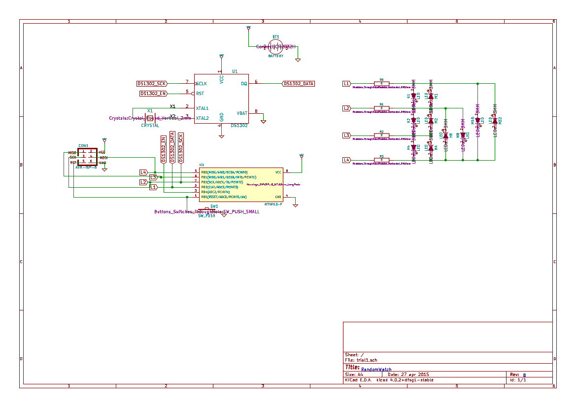
It's based on the RandomWatch schematics made by the people at RANDOM DATA.
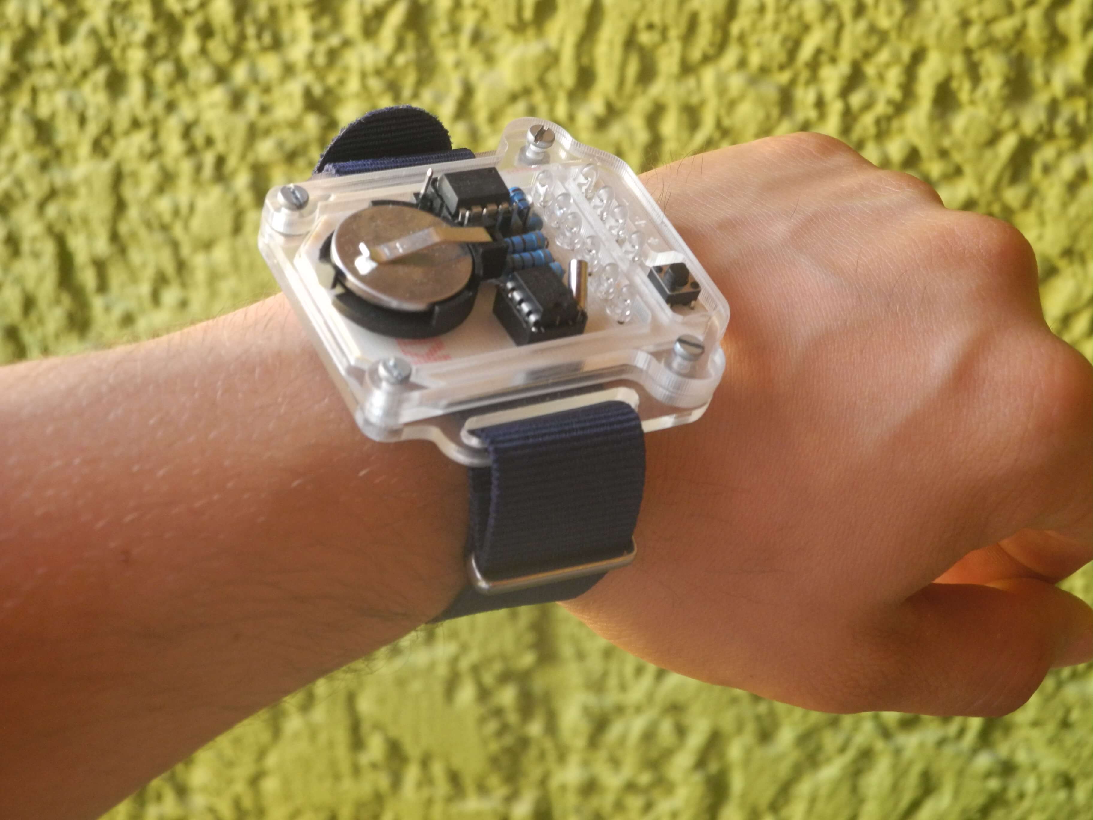
Pressing the button shows the time for some seconds (minutes on the left and hours on the right), then it shows the date and month (day on the left and moth on the right).
Circuit Description
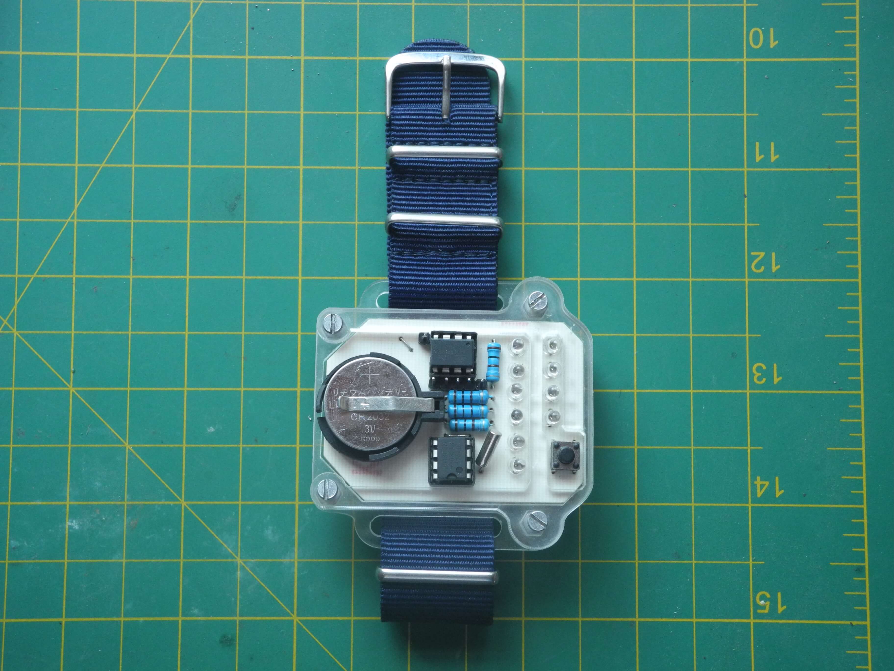
I followed the schematic provided by the folks at RANDOM DATA. It basically connects the attiny to the DS1302, and to the LED array through resistors. THe circuit is powered by a 3.3v coin cell (CR2032).
Since a watch's main constraint is space I chose to build the circuit in a PCB, although single sided since it was easier for me to etch it. The pcb files are also on GitHub).
I used though hole components because I had no experience with SMD soldering, but I think the circuit could definitely work with SMD technology and be made smaller, especially if a double sided PCB is used.
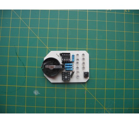
Since I wanted a different component arrangement than that of the RandomWatch I used Fritzing to create the PCB file to print. I chose it over other software like KiCAD because I had used it before to create breadboard diagrams and I did't want to invest the time to learn a new tool.
Due to space and single sided etching limitations, the ISP pins in the watch are not standard. Here's a pinout of the watch pins:
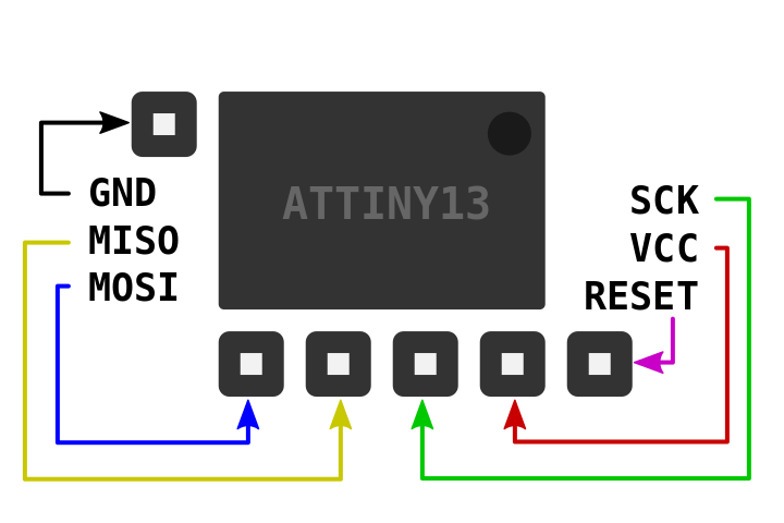
If this pinout does not makes sense and you are using an Arduino as ISP you can follow the wiring described on this instructable. The only pin headers not directly next to their corresponding ATTINY pin are the reset and ground pins.
Software
The watch's code basically makes the ATTINY read (or set) the time on the DS1302 and turn on the corresponding LEDs to display the time and date when the push button is pressed. After this, the watch enters into sleep mode util it's awakened by another button press.
To be able to program the ATTINY13 with Arduino I used MCUdude's MicroCore.
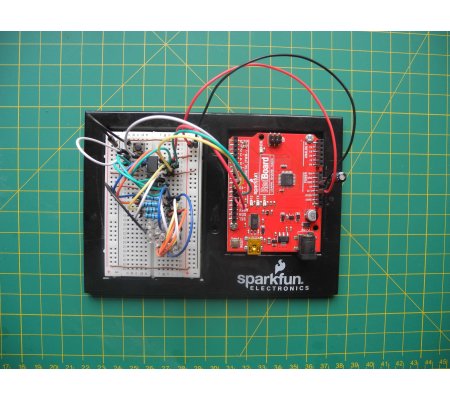
It is necessary to have an ISP programmer to upload the code to the watch, if you don't have one you can use your Arduino as one. To save battery life I made the ATTINY use its internal 128 kHz clock, so a small modification is needed in the Arduino ISP sketch file.
This line: #define SPI_CLOCK (1000000/6) should be changed to this: #define SPI_CLOCK (128000/6).
I used Charlieplexing to be able to switch the 10 LEDs on and off with 4 ATTINY pins.
Any ATTINY (with the same pinout) can be used, since the code fits into the ATTINY13 and does not use any function specific to the chip.
Materials
To make a watch just as the one showed, you will need access to a laser cutter (for the case) and a way to make PCBs.
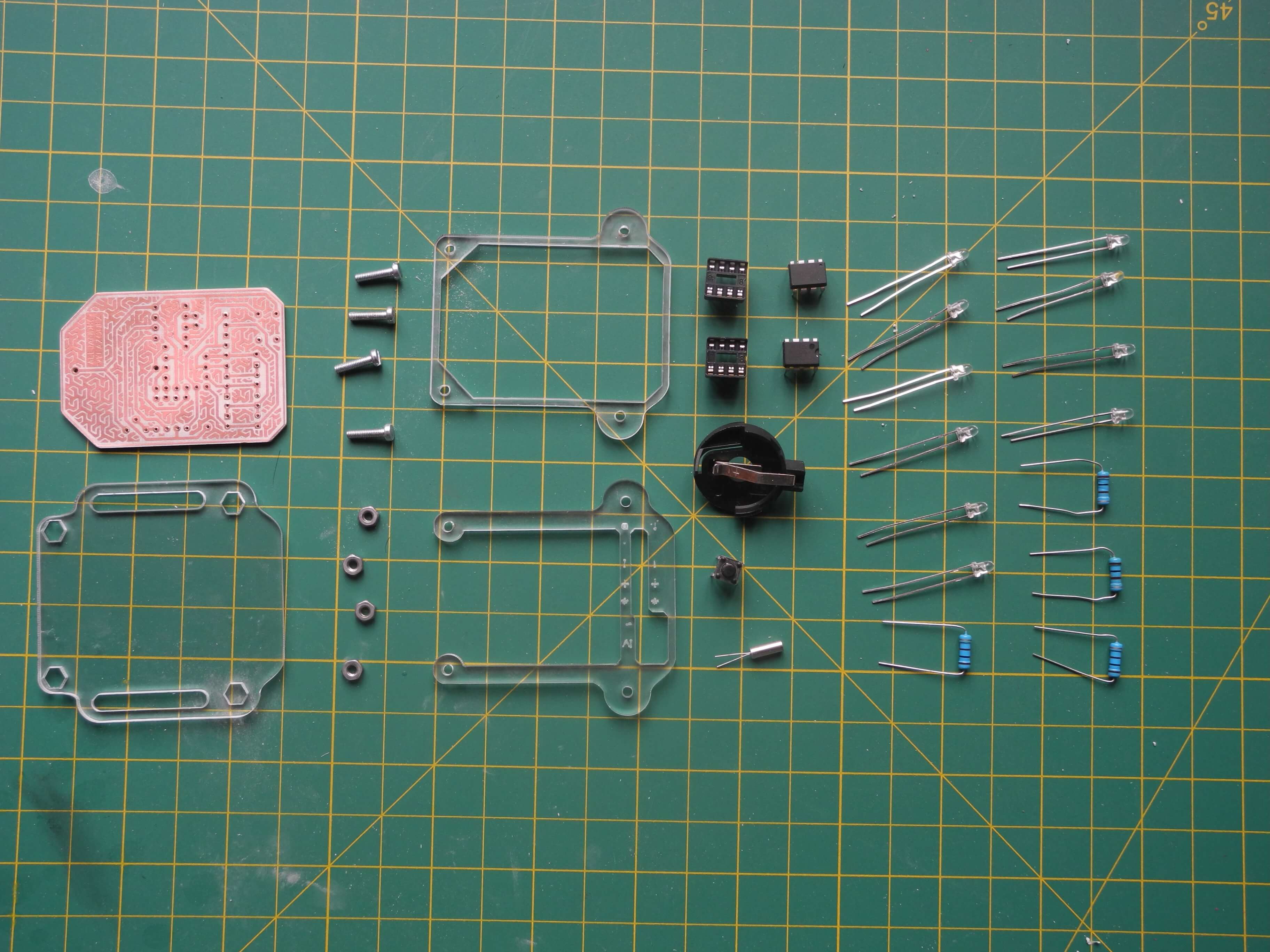
| You will need: | For this exact build: |
|---|---|
| 1 x ATTINY13 | laser cutter and 3mm transparent acrylic |
| 1 x DS1302 | 4 x 2mm screws (aprox. 10mm height) |
| 1 x 32.768kHz crystal | 4 x 2mm nuts |
| 1 x push button | Loctite (or any superglue) |
| 1 x CR2032 battery (not pictured) | a NATO style strap |
| 1 x CR2032 battery holder | |
| 2 x 8 pin IC sockets (optional for the fearless) | |
| 4 x 100 ohm resistors | |
| 10 x 3mm LEDs | |
| 6 x male header pins (not pictured) | |
| a way to make the PCB | |
| an Arduino (to use as ISP) |
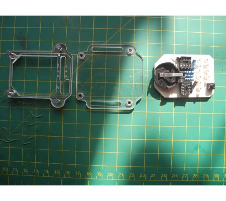
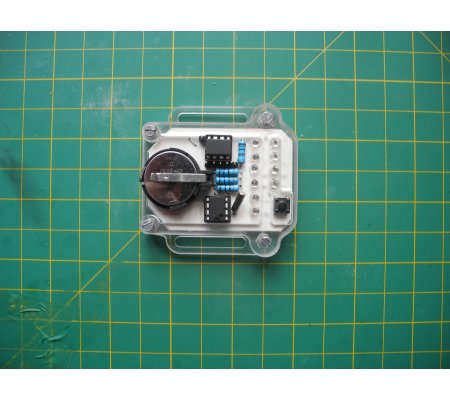
Mechanical construction
The case is made with 3 laser-cut pieces of transparent acrylic. I glued the nuts to the back part of the case to be able to hold it together with four screws.
Using the watch
While the design works and can be used on a daily basis, the desing is relatively fragile and not resistant to water or shock. Here are some considerations to have in mind when using the watch.
Setting the time
This is one of the main drawbacks of this design. In order to set the time on the watch the code needs to be reuploaded (so you need to be near a computer that has the Arduino IDE installed).
Battery Life
Right now the attiny binary watch draws 44uA when on sleep mode. This means that a regular CR2032 lasts for about 6 months.
Conclusion
The design needs a way to set the time without requiring a computer and the Arduino IDE.
I read more carefully the DS1302 datasheet after having constructed the circuit, and it seems that connecting pin 8 instead of pin 1 to VCC would greatly reduce the power consumption (the chip would consume 200nA instead of 15uA).
I have had the watch reset several times while wearing it. I suspect it is because the pins of the ISP header make contact with something, so this might be solved by using female headers instead of pins.