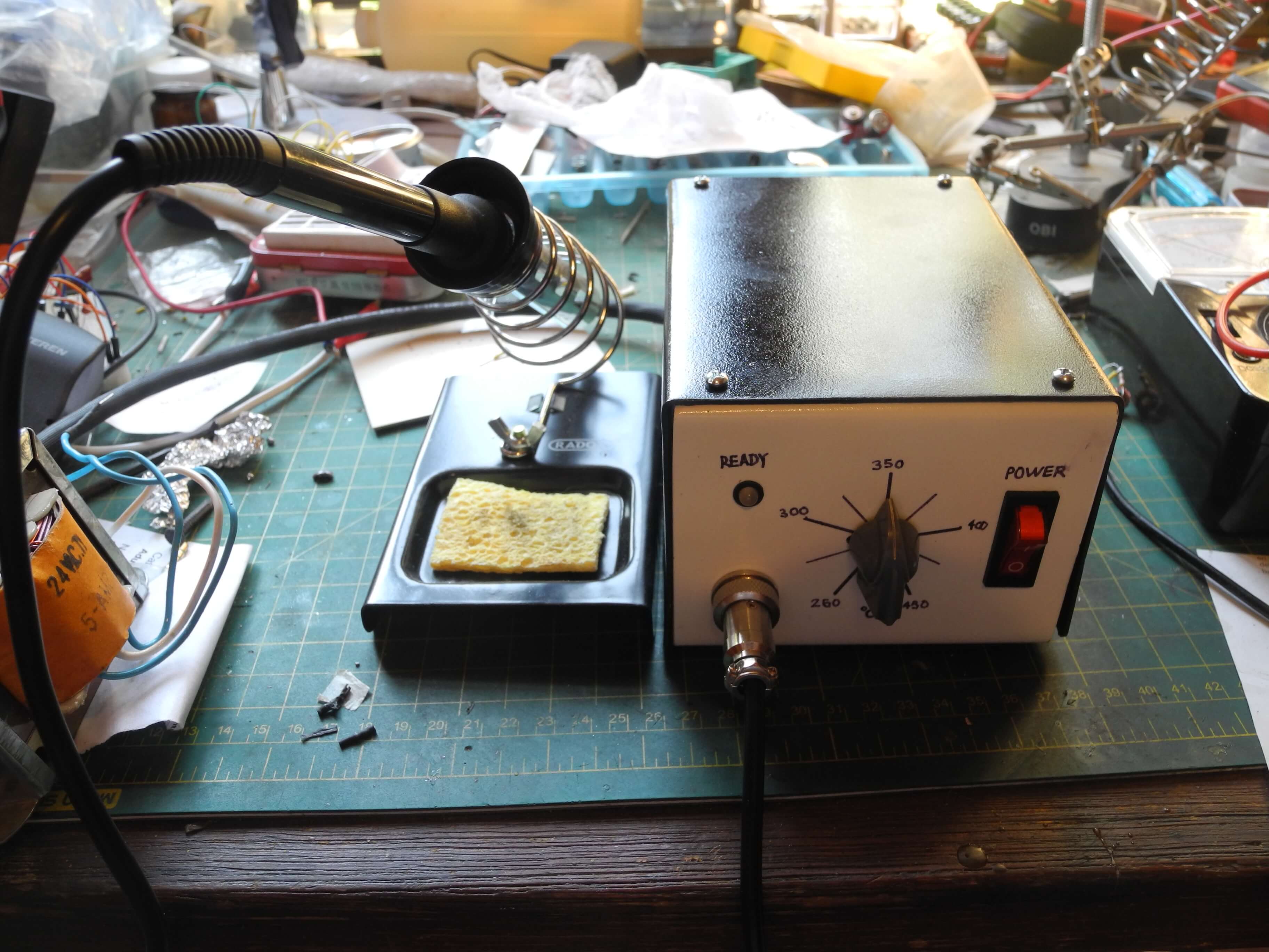
An analog soldering station with a controller based on an lm324 op-amp. You can find the KiCad files on GitHub.
Introduction
I have been using a cheap, variable power soldering iron for my electronics projects. I bought it when I didn't know if I would continue with the electronics hobby, and it has been very useful ever sice, but as I got more and more into electronics I thought on getting an upgrade.
But what were my options? Besides cheap non-regulated soldering irons, nowadays there are temperature soldering stations that can be bought off the internet for cheap. If you are not afraid to get your hands dirty, another option are the many different soldering station designs found on the internet, ranging from schematics of old hakko stations to various original (and sometimes confusing) designs.
As an electronic hobbyist, building an electronic tool seemed the way to go, so I started my quest to find a design amongst the chaos of the internet and build it as my next project. There were two main types of designs that I found while researching: Those based on a microcontroller and those based on analog components (op-amps mostly). I chose to build an analog station because I was interested in learning more about analog electronics, and I could find all the necessary components in my local electronics shop.
After studying many desings, I settled on the analog soldering station on this article from ZL2PD as my main inspiration. It appealed to me because it was a kind of PID controller for the iron temperature and seemed simple enough, so I built the circuit with a variable resistor instead of a thermistor to test it. Nevertheless, I wasn't totally convinced by the way the pulses for the heater control were generated, as they depended on a variable amplitude sawtooth wave that deformed and created a pulse that changed rapidly from about half duty cycle to almost 100% duty cycle.
After watching GreatScott's video on creating a boost converter without a microcontroller I realized that a similar circuit could be used to solve the problem of generating the heater control signal, so I started to work on creating a circuit based on that design. But besides adding another soldering station design to the plethora that can be found on the internet, I ended up learning a lot about operational amplifiers, triacs, and thermocouples.
Circuit Description
The circuit controls the temperature of the iron by controllig the power going into the heater with a triac switched by a PWM signal, the duty cycle of which depends on the difference between the desired temperature and the temperature measured by the thermocouple.
The PWM signal is generated by comparing this difference to a triangle wave, so that when the difference is higher the duty cycle is higher, and when the difference is lower the duty cycle is also lower.
Here's a representation of how the waveforms of the circuit should look (change the temperature with the slider at the bottom):
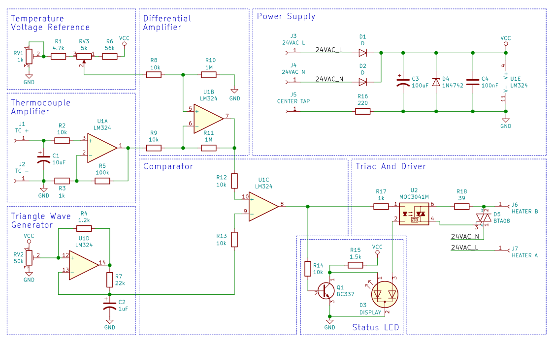
And here's a schematic of the circuit. All resistors are 5% 1/4 Watts, I used 1/2 Watts because those are the ones that my local electronics shop had. Note that the schematic is missing a connection of a 1Mohm resistor between the ground pin of the soldering iron handle and earth (for static protection).
Soldering iron handle
This is one of the central parts of the design, since the construction of the handle defines the required power supply, as well as the required logic for temperature control. I used a 907A soldering iron handle (much like ht eone described in this BigClive video, which is rated for 24v 50w.
This handle also uses a thermocouple as a temperature sensor. You can also find 907 (no A) handles which use a thermistor as a sensor, it is important to know which type you have as the methods for measuring its output are different. To know for sure measure the resistance of the sensor terminals at room temperature, if it's about 2ohms the sensor is a thermocouple, if it's between 40 and 50 ohms the sensor is a thermistor.
Using a heating element with a thermocouple sensor presented some challenges, given that I wanted to keep the component count to a minimum.
Thermal transfer issue
One of the main issues noted by people that use this kind of iron is the gap between the heating element and the iron tip. This causes the thermocouple to give an inaccurate temperature reading, and the iron to struggle to heat larger parts.
There's a solution to this problem proposed in this video that consists on using a thin copper sheet to fill the space between the tip and the heating element. I struggled to find copper metal sheet of a usable thickness, so I used a piece of soda can aluminum in its place and it seems to work fine (I removed the plastic and paint coating with paint thinner and sandpaper before using it in the iron).
Power Supply
I wanted the soldering station to be powered with 24v, and to keep the design as simple as possible I decided to use a transformer and heat the handle with AC. Since the resistance of the heating element was about 14 ohms I estimated it to have a maximum power consumption of 41w at 24v (a little over 1.7a) so I decided to use a 24v 2a transformer. The peak current on the mains side of the transformer was a little over 300mA, so I used a 500mA line fuse.
The transformer I got was center tapped, so I used 2 1n4007 diodes as a center-tap full-wave rectifier to get 12 volts for the board logic. This rectifier supplies about 19v unregulated dc, which is smoothed by a 100uF capacitor and then regulated by a 12v zener with a 220 ohm resistor, which limits the current through the zener to about 23mA. A 100nF capacitor is added to the regulated power lines to remove noise.
I decided to use a zener + resistor as a regulator because the current consumption of the logic was very low (about 20 mA) and I wanted to experiment with this configuration, the power supply could also be easily regulated with a 7812 IC.
Triac and Driver
Since I wanted to use AC to power the heating element, I needed a way to control the power reaching it. The anwer to this is to use a triac, which is like a pair of controllable diodes that can be activated like a transistor (more info on triacs here). But a triac needs to be activated with AC, and the temperature controller logic uses DC.
The solution to this problem is to use a triac driver, a type of optocoupler, to switch the AC for the triac with a DC circuit (more info on optocouplers here). This type of circuit could be considered a solid state relay.
I used a BTA08 triac driven by a moc3041. Since the triac is driving a resistive load it only needs a resistor between the live/load terminal of the triac and the driver's photo-triac controlling the gate. The 39 ohm value was chosen according to the formula described in the answer on this Stack Overflow post. The moc3041 emmiter is connected in series with an indicator LED and a 1k current limiting resistor (to limit current to about 9mA).
The moc3041 is similar to the moc3021, but it has built-in zero-crossing detection, which only turns on the triac when the ac wave is at (or near) zero volts so that there are no sudden surges in current.
I would recommend using a triac with the lowest possible voltage drop, specially if the handle is powered by 24vac, since any voltage drop will be reflected in the maximum power of the iron.
Thermocouple amplification
Since the soldering iron handle thermocouple is a type K (I think) it produces voltages between 0mV and 19mV in the rage of 0 to 450 (which was the range that was useful for this project). This means the signal needs to be amplified before using it with the differential comparator, otherwise the amplification of the comparator would have to be too high (and may lead to signal distortion).
I used one of the lm324 op-amps as a non-inverting amplifier with a gain of about 100, determined by resistors R3 and R5. R2 and C1 act as a low pass filter allowing only signals below 1.6 Hz, to eliminate input noise.
Differential amplifier
The differential amplifier takes as inputs both the output of the amplified thermocouple signal and the output of the voltage divider created by RV1, RV3, R1, and R6. It then amplifies the difference between those voltages by a factor of 100, determined by Resistors R8, R9, R10, and R11.
RV1 and R1 define the lowest temperature level, while R6 defines the highest. RV1 is used to calibrate the iron temperature.
The output of this circuit is used as one input of the comparator.
Triangle Wave Generator
The other input for the comparator is a 10Hz triangle wave generated with a single op-amp. Since I was already using 3 out of the 4 opamps in the lm324, I decided to use the single op-amp triangle wave generator described in this PCB isolation article. It works fine for this application, but the drawn current from the circuit must be kept to a minimum.
Why 10Hz? Because it is a frequency that allows for fast readings and changes while maintaining a decent definition of the PWM signal. To clarify, since the moc3041 only turns on at the zero point of the ac wave it can be turned on at a maximum rate of 120Hz (for 60Hz mains). This means that a PWM signal with a duty cycle depending on a 1Hz triangle wave lets a maximum of 120 ac half-waves pass, and has 120 possible duty cycle levels. So a 10Hz signal allows for a maximum of 12 ac half-waves to pass, and has 12 possible duty cycle levels.
RV2 is used to control the symmetry of the triangle wave, it should be set at or near the middle range of the potentiometer.
Comparator
The last op-amp is used as a comparator to create the PWM signal used to drive the triac. This signal is high when the output of the differential amplifier is higher than that of the triangle wave generator, and low otherwise.
Therefore the duty cycle of this signal, and that of the heating element, increases as the difference between the iron temperature and the desired temperature is higher and decreases when it's lower.
Display LED
I used a bi-color LED. The red LED is connected in series with the emitter of the moc3041, so when the heater is on the red led turns on. A npn transistor was used as an inverter, or not gate, to light the green LED when the heater was off.
The bi-color LED could be replaced by two regular LEDs or, if desired, a single LED can be used to only show when the heater is on and leave out the transistor Q1, the green LED, and the current limiting resistor R15.
Mechanical construction
I imitated the desing of the cheap hakko clones, but I used metal instead of plastic because it is an easier material to work with (at least for me). The case was constructed using two pieces of bent steel with openings for the inputs and controls, and tapped holes to join the two parts together with screws.
A friend who works with metal professionally helped me build the case, but the tools we used weren't really sophisticated, we didn't even use a metal brake. The bends were made with a metal workbench, clamps, pieces of wood and a hammer.
Since I used steel I coated the case with zinc-rich paint to avoid rust, and then painted the case and clear coated it. I think aluminum is better for case construction, but I used steel since that was what my friend had as metal scraps.
The main factor for me to decide not to mount the pcb on the front panel of the enclosure, as many soldering stations do, was that I could not (locally) find a potentiometer that I could mount vertically on the PCB, the potentiometers I found had legs that were too short to bend them so they could be mounted the way I needed. Instead, the PCB was mounted to the bottom of the case using pieces of thin PVC tubing as spacers, also, the underside of the PCB was protected by using a thin solid plastic layer held with the same screws as the PCB.
The control markings were made with a sharpie over the paint coat and before applying the clear coat layers.
Conclusion
There are a couple of drawbacks on this design. Firstly, there seems to be a noticeable thermal lag between the iron tip and the thermocouple, which makes the iron take longer to heat. Nevertheless this effect is lessened by the modification described on the soldering handle section.
Another change I would make to the design is the bi-color LED, because it lights in a yellow hue when the iron reaches the desired temperature. I would probaly choose to use a single LED to show when the heater is on, since having a more precise indicator of when the iron has reached the desired temperature with analog components would call for an increase in component count.